10.4.2. Real-time control with the Simulink® block
When a user generates a new solver, a Simulink® block becomes available in the interfaces folder. Such block is useful to interface the solver with other Simulink® models for simulation, or for deployment to embedded prototyping hardware using tools such as dSPACE MicroAutobox or Simulink® Coder.
10.4.2.1. Input and Output Ports in the Compact Interface
For every solver, there are two Simulink® variants generated: a standard variant; and a compact variant, which groups parameters and outputs. For problems with many parameters and outputs, the compact variant is more suitable because it reduces the number of ports and connections that need to be wired up to the rest of the Simulink® model.
The criteria for grouping parameters is the following: parameters of the same type that have the same number of rows are grouped together into a single
stacked parameter. These parameters are stacked horizontally, e.g. if there are two parameters mapping to eq.c, both of size 3x1, they will be
grouped into a new parameter of size 3x2. The new parameter will get the name c.
To illustrate the conversion, consider a problem with the following parameters and with the corresponding standard (non-compact) Simulink® block:
Name |
maps2data |
Dimensions |
|---|---|---|
|
|
2x4 |
|
|
3x4 |
|
|
3x4 |
|
|
3x4 |
|
|
4x1 |
|
|
4x1 |
|
|
4x1 |
|
|
4x1 |
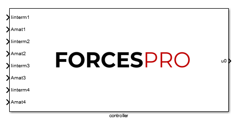
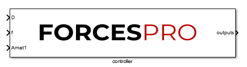
For the compact Simulink® block, parameters linterm1, linterm2, linterm3 and linterm4 are stacked together into a new parameter f
(because the problem data they map to is cost.f). For the parameters mapping to eq.D, Amat2, Amat3 and Amat4 can be stacked into
the new parameter D. Amat1 is not included into the new parameter because it has two rows and the concatenation is not possible with the other
parameters, which all have three rows. Parameters are always stacked horizontally according to the stage number they map to.
Name |
maps2data |
Dimensions |
|---|---|---|
|
|
3x12 |
|
|
4x4 |
|
|
2x4 |
The port dimensions of any FORCESPRO Simulink® block can be checked by double-clicking the block and clicking the ‘Help’ button.